Mini DC motors power familiar objects, from camera lenses and cooling fans to small pumps and robotic joints. Yet one basic question often receives an incomplete answer: how does a mini DC motor work? In simple terms, electrical current creates a magnetic field inside the motor. That field pushes against permanent magnets or another magnetic field. The resulting force turns the rotor, while the commutator and brushes keep the torque moving in one direction.
The details matter. A motor may spin at 10,000 revolutions per minute, but speed alone does not prove good performance. Load, voltage, current, friction, heat, and brush wear all affect real output. The International Energy Agency has reported that electric motor-driven systems consume roughly 45% of global electricity. Even small motors therefore deserve efficient design and careful control. Grand View Research also identifies continued growth in global DC motor demand, driven by automation, appliances, vehicles, and compact equipment.
This guide presents seven practical tips for understanding motor operation. It connects electromagnetic theory with visible details, such as a vibrating fan blade, warm winding, or sudden voltage drop. The explanations follow engineering principles used in IEC 60034 motor standards, while recognizing a common weakness: simplified diagrams often hide losses and starting current. That limitation matters. A mini motor is not merely a smaller industrial motor. Its narrow windings heat quickly, and tiny manufacturing differences can change noise, torque, and service life. Real testing is essential.
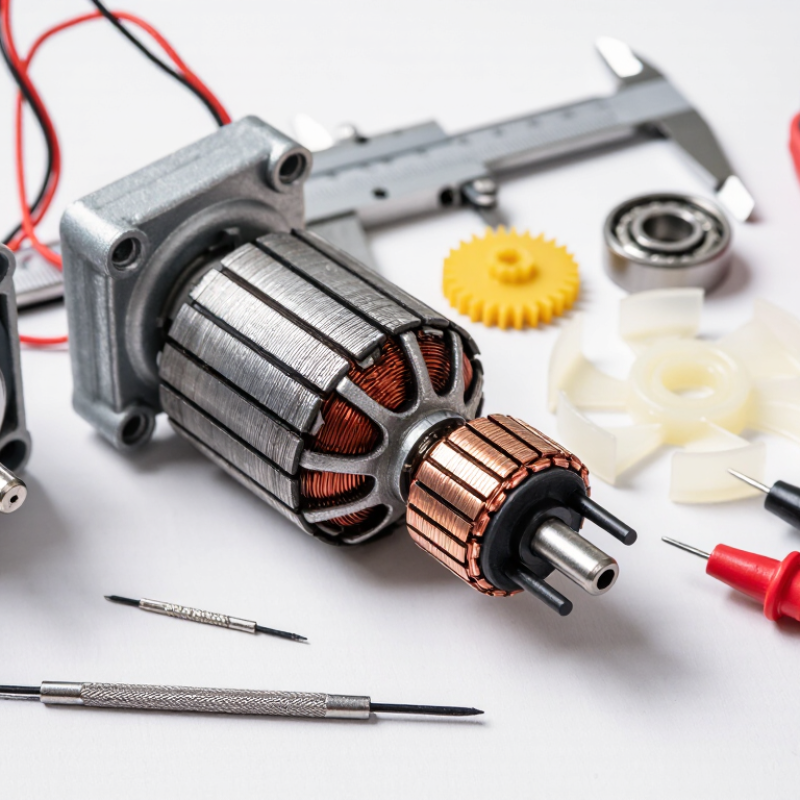
A mini DC motor is a compact machine that changes electrical energy into rotary motion. It usually runs from low-voltage direct current supplied by batteries or a control circuit. Inside its metal or plastic housing, several small parts work together with surprising precision.
The stator provides the stationary magnetic field. In many mini motors, this field comes from two permanent magnets fixed inside the housing. The rotor, also called the armature, carries copper windings and turns around a central shaft. When current enters the windings, they become temporary electromagnets. Their interaction with the stator field creates torque, which spins the rotor and shaft.
The brushes transfer current from the fixed terminals to the rotating commutator. The commutator changes the current direction in each winding as the rotor turns, keeping the torque moving forward. Small bearings or bushings support the shaft and reduce friction. The housing holds everything in alignment, although tiny misalignment can cause noise or vibration.
In practical testing, a motor may spin freely but slow sharply under load. That difference matters. Voltage influences speed, while load and friction influence current and heat. A simple diagram can make operation look effortless. It is not. Brush wear, dust, and weak connections can reduce performance, so measuring current and temperature is safer than guessing. A motor’s real behavior often differs slightly from its printed specifications.
| Tip | Main Part or Concept | What It Does | How It Works | Typical Information | Practical Check |
|---|---|---|---|---|---|
| 1 | Permanent-Magnet Stator | Provides a stationary magnetic field around the rotating armature. | Permanent magnets create fixed north and south magnetic poles. The armature’s magnetic field interacts with them to produce torque. | Common in compact brushed motors because it is simple, lightweight, and does not need a separate field winding. | Keep magnets away from excessive heat and strong external magnetic fields. |
| 2 | Armature and Copper Windings | Converts electrical current into a rotating magnetic field and mechanical torque. | Current flowing through the windings creates an electromagnet. The force on a current-carrying conductor in a magnetic field causes the rotor to turn. | The armature is usually made from laminated steel to reduce eddy-current losses; copper wire is commonly used for the coils. | Overloading increases winding current, heat, and the risk of insulation damage. |
| 3 | Commutator | Reverses the current direction in the armature coils at the correct rotor position. | Segmented copper sections switch coil connections as the rotor turns, keeping the torque in the same rotational direction. | A brushed DC motor commonly uses a multi-segment commutator mounted on the rotor shaft. | Visible sparking, rough rotation, or heavy wear can indicate commutator contamination or excessive brush wear. |
| 4 | Carbon Brushes | Transfer electrical current from the stationary terminals to the rotating commutator. | Spring pressure keeps each brush in contact with the commutator while allowing the rotor to spin. | Brushes are wear parts. Their service life depends on current, speed, pressure, temperature, and commutator condition. | A motor that starts intermittently may have worn brushes, weak springs, or a dirty commutator. |
| 5 | Shaft, Bearings, and Bearings Supports | Transfers torque to the external load and keeps the rotor accurately aligned. | Bearings or bushings reduce friction while supporting radial and limited axial loads on the shaft. | Small motors may use sleeve bushings or ball bearings. Shaft speed can range from several thousand to tens of thousands of revolutions per minute, depending on design and load. | Excessive side load, misalignment, or poor lubrication can increase noise and reduce efficiency. |
| 6 | Electrical Input and Back EMF | Determines the motor’s available speed, torque, and power. | Applying DC voltage produces current and torque. As the motor spins, it generates back electromotive force that opposes the supply voltage and limits current. | At startup, back EMF is nearly zero, so the initial current can be much higher than the running current. | Use the rated voltage and limit stall time to prevent overheating from high startup or locked-rotor current. |
| 7 | Speed, Torque, and Efficiency | Describes how the motor responds when the mechanical load changes. | Increasing load generally reduces speed and increases current. Motor output power is calculated as P = T × ω, where T is torque and ω is angular speed. | Efficiency is below 100% because of copper loss, brush friction, bearing friction, magnetic loss, and windage. | Choose a motor by comparing rated voltage, no-load speed, rated speed, rated torque, current, and allowable temperature. |
It converts low-voltage electrical energy into rotary motion. A small shaft turns.
The stator creates a stationary magnetic field. Permanent magnets often provide it.
Copper windings carry current and become temporary electromagnets. Their interaction creates torque.
Brushes transfer current to the rotating commutator. The commutator reverses current at the right moment.
The rotor may stop after half a turn. Continuous rotation would fail.
A stopped rotor produces little opposing voltage. Starting current can therefore rise sharply.
A heavier load requires more torque and current. Speed drops, while heat may increase.
Measure voltage, resistance, current, and temperature. Also inspect brushes, dust, bearings, and shaft alignment.
Yes. It may slow under load because of friction, weak connections, or worn parts.
They may blame the motor too quickly. A loose wire once looked like a failed motor.
Understanding how does a mini DC motor work begins with its basic parts: a stator, rotor, coils, commutator, brushes, shaft, and housing. When electrical current flows through the motor coils, it creates magnetic fields that interact with the permanent magnetic field around them. This attraction and repulsion produce torque, causing the rotor and attached shaft to turn.
The commutator and brushes continuously switch the current direction in the coils, helping the rotor maintain smooth rotation instead of stopping after a half-turn. For reliable operation, use the correct voltage, avoid excessive loads, check that the shaft turns freely, and keep electrical connections clean and secure. During testing, increase power gradually, monitor heat and unusual noise, and disconnect the motor if it shows signs of strain. These practical steps make it easier to understand motor behavior, identify common problems, and improve safe, consistent performance.

 KPM Minimoto