Small DC motors can look simple, but improving their performance takes more than raising the voltage. A motor that spins faster may also run hotter, draw more current, or wear out sooner. The useful target is balanced performance: suitable speed and torque, stable operation, and acceptable temperature. Small details matter. A bent shaft, tight gearbox, or undersized power supply can quietly waste output.
Austin Hughes, author of Electric Motors and Drives, provides a useful engineering perspective. Paraphrased, his guidance is: “Match the motor, load, and control method before pursuing higher speed.” That principle frames how to improve mini DC motor performance without relying on guesswork. Start by measuring the motor under its actual load. Record voltage, current, speed, and temperature, then change one factor at a time. A simple tachometer and multimeter can reveal whether a problem comes from the supply, friction, or the application.
There is no universal upgrade. Correct alignment, low-friction bearings, suitable gearing, and a well-sized driver can each help, but the best choice depends on the motor and task. PWM control may improve speed adjustment, yet poor settings can introduce noise or extra heat. Check the manufacturer’s limits, and retest after every change. Small gains count. So do trade-offs. A setup that performs well on a workbench may behave differently after minutes inside a warm enclosure. Careful measurements—not assumptions—make improvements repeatable, though even a tidy test may miss a real-world vibration or load change.
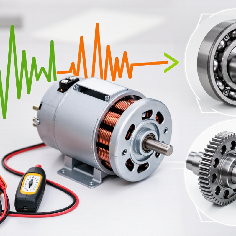
Mini DC motor performance depends on the match between voltage, load, and motor design. Raising voltage may increase speed, but it can also raise current and heat. Stay within the motor’s rated limits. A motor turning freely on a bench may slow sharply when driving a wheel, gear, or small pump. Measure speed under the actual load, not just with the shaft uncovered. Compare current readings too; a sudden increase can signal excess friction or an unsuitable load. Heat matters.
Winding resistance, magnet strength, bearing condition, and commutation all influence torque and efficiency. So do mounting and alignment. A slightly bent shaft or tight gear mesh can waste energy as vibration and warmth. Check that the motor sits squarely and that connected parts rotate without binding. Small changes count. For repeatable tests, use the same supply voltage, load, and run time, then record speed, current, and case temperature. Allow cooling between trials. This is not always convenient, and brief tests can miss heat buildup during longer operation. A simple comparison under realistic conditions often reveals more than a single advertised speed figure.
| Performance factor | What to measure | How it affects performance | Practical improvement |
|---|---|---|---|
| Supply voltage | Voltage at the motor terminals while it is running (V) | For a brushed DC motor, no-load speed is approximately proportional to applied voltage within the motor’s operating range. Voltage drop in wires or the power source can reduce speed and available performance. | Use a supply within the motor’s rated voltage. Measure voltage at the motor under load and reduce losses from undersized wires, connectors, or an overloaded supply. |
| Load torque and current | Shaft torque (N·m) and operating current (A) | Motor torque is approximately proportional to armature current. A higher mechanical load generally requires more current and can lower rotational speed. | Reduce unnecessary friction and mechanical load. Select a motor and gearbox with suitable continuous torque rather than relying on stall torque. |
| Winding resistance and heating | Winding resistance (Ω), current (A), and winding or case temperature (°C) | Winding copper loss is approximately P = I²R. Higher current increases heat rapidly; excessive temperature can shorten motor life and may damage insulation. | Keep continuous current and temperature within the motor’s specifications. Improve airflow or heat transfer where appropriate, and avoid prolonged stall or overload. |
| Efficiency | Electrical input power (W) and mechanical output power (W) | Efficiency is η = mechanical output power ÷ electrical input power × 100%. Mechanical output power for rotation is P = torque × angular speed. | Operate near the motor’s efficient working range, minimize friction, and avoid choosing a motor that is substantially oversized or undersized for the load. |
| Speed control and PWM | PWM duty cycle (%), motor-terminal voltage, and loaded speed (rpm) | PWM controls average motor drive by switching the supply on and off. Speed does not always change linearly with duty cycle because load, motor characteristics, and driver voltage drops also matter. | Use a suitable PWM motor driver and verify speed under the actual load. Check that the driver’s current rating can handle the motor’s operating and startup current. |
| Driver and power-source capacity | Driver current rating, supply voltage, and voltage sag during startup (V) | A current-limited driver or a supply that sags under load can prevent the motor from starting or reaching expected speed. Startup current can be much higher than normal running current. | Check the motor datasheet for startup or stall current. Choose a driver and supply with appropriate ratings and suitable protection against overcurrent. |
| Bearings, alignment, and friction | No-load current, shaft free movement, vibration, and noise | Misalignment, excess bearing friction, or rubbing parts consume torque and power, leaving less output available to the driven load. | Align the motor shaft with the load, avoid excessive radial or axial force, and use compatible lubrication only where the motor design permits it. |
| Gear ratio and driven load | Gear ratio, output speed (rpm), and output torque (N·m) | A reduction gearbox trades output speed for increased output torque, with some power lost to gear friction. The motor must still remain within its permissible speed and torque limits. | Choose a ratio that meets the required output speed and torque. Account for gearbox efficiency and avoid loading the motor beyond its continuous rating. |
Note: Relationships shown are general engineering principles. Actual speed, torque, current, temperature limits, and efficiency depend on the specific motor, driver, supply, and mechanical load; consult the motor datasheet for rated values.
Check its torque-speed curve, rated voltage, and continuous current. A geared mechanism may need a brief startup surge.
It must provide running current and tolerate startup demand. If voltage sags, the motor may start slowly or stall.
No-load current can be misleading. Test the motor with its mechanism attached, especially if parts may bind.
Yes. PWM can reduce average motor voltage, but switching and wiring losses still matter.
Misaligned shafts, dry bearings, dust, or a rubbing fan can add friction. A tiny rub matters.
Match bearings to speed, load, and mounting position. Keep couplings aligned, and avoid excess lubricant or pressure on the end bell.
It may suggest less friction, but it does not prove better performance under load. That distinction is easy to miss.
Run the motor under repeatable conditions and record the case temperature and sensor location. Let it cool between tests.
Reduce the load or duty cycle, then retest. Also inspect the windings, bearings, and ventilation; adding a fan may only mask the problem.
Improving a mini DC motor starts with understanding the factors that shape its performance, including load, operating voltage, current, speed, and the motor’s intended use. Selecting a motor and power supply that suit the application helps provide reliable operation without placing unnecessary strain on the motor. A well-matched setup also makes it easier to balance torque, speed, and energy use.
A practical guide to how to improve mini DC motor performance should also cover careful voltage and speed control, reducing friction in moving parts, and managing heat through suitable operating conditions and airflow. Regular testing can reveal changes in speed, temperature, or noise before they affect reliability. Keeping the motor clean, checking connections, and maintaining mechanical components help preserve consistent performance over time.

 KPM Minimoto